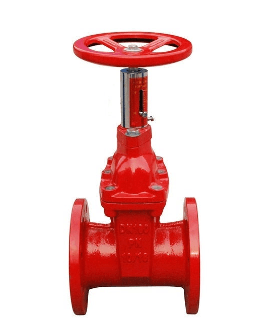
Manual Valve Operation Structures
3 min read
Manual Operation Structures
Common Types
Apart from the common round handwheel, manual operations also include:
- Handle:
- Suitable for small torque 90° rotating valves.

- Suitable for small torque 90° rotating valves.
- Manual Rod:
- Suitable for high torque 90° rotating valves without using a driving device. An extension rod can be used if necessary.

- Suitable for high torque 90° rotating valves without using a driving device. An extension rod can be used if necessary.
- Oval Handle:
- Suitable for 90° rotating valves.

- Suitable for 90° rotating valves.
Chain Wheel
Structure

- Components:
- Chain wheel, protective frame, chain.
- Features:
- The chain is wound around the chain wheel through a protective frame mounted on the bracket. It operates smoothly, reducing radial jumping and vibrations, which prevents damage to components and extends the life of the chain wheel drive.
- Applications:
- For operating valves located at high positions or requiring remote control.
- Suitable for horizontal stem globe valves or gate valves.
Universal Joint

Structure
- Mechanism:
- Utilizes spherical devices to achieve non-coaxial axial power output. The output shaft rotates around its axis and transfers this rotation through the universal joint to the input shaft, which also rotates around its axis. This enables driving valves not aligned on the same axis.
- Applications:
- Suitable for limited installation operation positions.
Impact Handwheel
For gate and globe valves, impact handwheels can be used to increase operational force.

- The handwheel has a rotational gap with the impact block. During the instant of opening or closing the valve, the handwheel generates impact force, which drives the stem nut with significantly greater force than a standard handwheel. Impact handwheels can produce 1-5 times the force of a regular handwheel.
Locking Structures
Locking structures prevent accidental operation by locking the handwheel in a specific position.
Gate and Globe Valve Locking Structures
- Handwheel Locking Structure:

- Suitable for handwheel-operated gate and globe valves.
- The baffle is connected with the chain, which is wound around the handwheel spoke and connected to the baffle shaft welded on the valve bracket. A copper padlock is used to lock it.
- Gearbox Handwheel Locking Structure:
- Suitable for gate and globe valves.
- The gearbox comes with a locking structure and is locked by a lock.
1/4 Turn Valve Locking Structure (Ball Valves)

- Ensures the valve is lockable in fully open and fully closed positions to prevent accidental operations.
Position Indication
Position indicators show the valve's position (fully open, fully closed, or proportionally open).
Types of Position Indicators
- Dust Cover Handwheel Indicator:

- Suitable for gate valves with dust cover structures.
- A hole is drilled on the stem top, and an indicator rod with threaded ends is screwed in. A scale glass cover and indicator board are fixed on the dust cover. The stem movement drives the indicator rod and board to show the valve position.
- Indicator Nut Position:

- Used for ground valves or raised operation devices.
- The handwheel drives a shaft connected to the stem nut through a meshed connection. The shaft rotation controls the indicator nut's rise and fall, which, in turn, shows the valve position.
- Indicator Sleeve Position:

- Applied to rotating lifting stem valves like globe valves.
- The indicator sleeve is fixed with the handwheel and moves with the valve stem to show the valve position.
- Non-rising stem Gate Valve Indicator:

- A threaded stem works with an indicator nut, which moves along a fixed guide slot, showing the valve position.
- Handle Position Indicator:
- Suitable for ball valves.

- Suitable for ball valves.
- Gearbox Position Indicator:

- Suitable for ball and butterfly valves with gearboxes.
Positioning Structure
Similar to the locking structure, the positioning structure ensures the valve remains in position even after the handle or gearbox (actuator) is removed. It includes full open and full close positioning
Conclusion
Manual operation structures for valves include a variety of handwheels, handles, rods, and other mechanisms to facilitate different operational needs and constraints. Locking structures ensure safety and prevent unauthorized or accidental operations. Position indicators provide visual feedback on valve status, enhancing operational accuracy and safety.
FAQs
- What is the primary purpose of the chain wheel structure in valve operations?
- The chain wheel structure is used to operate valves positioned too high or requiring remote control, ensuring smooth operation and reducing component wear.
- How does the impact handwheel increase operational force?
- The impact handwheel generates impact force through a rotational gap with the impact block, providing significantly greater force than standard handwheels.
- Why are locking structures important for manual valves?
- Locking structures prevent accidental or unauthorized valve operations by securing the handwheel in a specific position.
- What types of valves commonly use position indicators?
- Position indicators are commonly used in gate, globe, ball, and butterfly valves to show their open or closed status.
- Can the handwheel installation orientation for driving devices be adjusted?
- Yes, the handwheel installation orientation can be adjusted with four standard directions available for convenience.


